Explore our heavy-duty, variable frequency driven motors engineered for extreme thermal endurance and peak efficiency.
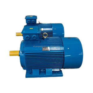
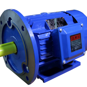
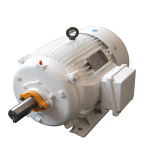
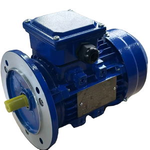
Delivering high-reliability power, application-matched customization, and total lifecycle security.
Over 50 years of specialized motor engineering. We tailor winding topologies, shaft configurations, and insulation systems specifically for variable speed frequency drives (VFDs).
Our expansive global logistics framework guarantees localized inventory buffer storage, mitigating lead time risks for critical industrial plant downtime and OEM production runs.
Full compliance with marine and industrial certifications (DNV, ABS, LR, BV, ATEX, IECEx, and NEMA MG1 Part 31). Built to withstand high ambient temperatures, vibration, and humidity.
Modern industrial automation relies heavily on Variable Frequency Drives (VFDs) to regulate motor speed, maximize operational process control, and conserve electrical energy. However, driving standard AC induction motors with Pulse Width Modulated (PWM) inverters imposes severe stress on internal mechanical and electrical components. A dedicated Custom OEM Inverter Duty Motor is specifically engineered to mitigate these stresses and deliver zero-defect reliability across broad turn-down speed ranges.
When powered by a VFD, high-frequency switching transistors (IGBTs) generate rapid voltage rise times ($dv/dt$). This voltage wave behavior creates sharp voltage spikes across the initial turns of the motor winding, often exceeding the dielectric strength of conventional magnet wire insulation. Over time, partial discharge (corona) degrades standard enamel coating, culminating in short-circuits and catastrophic winding failure.
| Performance Characteristic | Standard General-Purpose Motor | OEM Custom Inverter Duty Motor |
|---|---|---|
| Insulation System | Class F (Standard Enamel, Dip & Bake) | Class H Inverter-Grade (VPI / Corona-Resistant) |
| Insulation Surge Resistance | Up to 1000V Peak Voltage | 1600V to 2200V Peak Voltage (NEMA MG1 Part 31) |
| Thermal Management at Low RPM | Self-ventilated (Cooling degrades with RPM) | Forced Blower Cooling (IC416) / Constant Torque Capability |
| Bearing Protection | Standard Steel Ball Bearings | Insulated Bearings / AEGIS® Shaft Grounding Rings |
| Constant Torque Turndown Ratio | 4:1 or 10:1 | 20:1 up to 2000:1 (Closed-Loop Encoder Feedback) |
To eliminate corona inception, our advanced OEM manufacturing facilities deploy Class H Inverter-Grade Magnet Wire reinforced with inorganic phase insulation and double-dip Vacuum Pressure Impregnation (VPI) epoxy resins. This robust construction ensures that voltage transients up to 2000V are absorbed safely, guaranteeing long insulation service life even under long cable lead runs where reflected wave phenomena multiply voltage peaks.
A frequently overlooked failure mechanism in variable speed drive systems is electrical bearing fluting caused by Common-Mode Voltage (CMV). Because the sum of the three-phase output voltages from a PWM inverter does not equal zero, a neutral voltage shift is induced on the motor rotor shaft. When this capacitive charge builds up to a critical threshold, it discharges through the thin oil film of the bearings to the grounded motor frame.
These micro-arcing events—known as Electrical Discharge Machining (EDM)—create microscopic pit marks and frosted track patterns along the bearing raceways. Left unaddressed, EDM causes premature bearing noise, excessive vibration, lubricant breakdown, and complete mechanical seizure.
As industrial enterprises transition toward Net-Zero carbon targets and Smart Manufacturing 4.0 standards, procurement strategies for electrical machinery are evolving rapidly. B2B buyers, global EPC contractors, and OEM machinery builders are no longer evaluating acquisition costs (CapEx) in isolation. Instead, total lifecycle cost (OpEx) analysis dominates procurement decisions.
Key procurement vectors currently driving custom OEM motor factory partnerships include:
A. Transition to IE4 & IE5 Ultra-Premium Efficiency Compliance: European Union eco-design directives (IEC 60034-30-2) and regional energy standards are mandating minimum IE4 efficiency levels for motors operating within continuous duty cycles. OEMs are integrating Synchronous Reluctance (SynRM) and Permanent Magnet (PM) technologies to achieve peak partial-load efficiency under variable speed controls.
B. Demand for Sensor-Integrated "Smart Motors": Modern inverter duty motors are delivered from the factory pre-fitted with vibration transducers, bearing temperature probes (PT100/RTC), and micro-IoT gateways. This enables real-time condition monitoring, predictive maintenance alerts, and seamless integration into factory SCADA systems.
C. Resilient Dual-Sourcing and OEM Tailored Modular Platforms: Supply chain disruptions have highlighted the vulnerability of single-region procurement. Global buyers are seeking certified OEM partners capable of supplying modular motor platforms—allowing quick adjustments to shaft dimensions, terminal box locations, brake additions, and forced-cooling kits on short notice.
Looking ahead, inverter duty motor manufacturing is entering a dynamic era driven by advancements in power electronics and materials science:
Addressing the critical engineering & sourcing queries raised by OEM buyers and plant engineers.
An "Inverter Rated" motor is typically a standard motor upgraded with Class F or H insulation that can handle limited speed turn-down (e.g., 4:1 or 10:1 variable torque). A true "Inverter Duty Motor" meets NEMA MG1 Part 31 standards, utilizing specialized corona-resistant magnet wire, insulated bearings, shaft grounding, thermal protection sensors, and optional forced ventilation (external blowers) to operate continuously across extreme speed ranges (up to 2000:1 constant torque) without overheating or insulating dielectric failure.
Standard motors rely on an internal shaft-mounted cooling fan (IC411). When a motor operates at low speeds driven by a VFD, airflow drops drastically proportionally to the speed decrease while heating losses remain high under full torque demands. A forced cooling blower (IC416) operates independently at a constant speed, maintaining continuous airflow across the motor cooling fins regardless of the primary motor shaft RPM.
Long cable runs (typically exceeding 50 to 100 feet) exacerbate reflected voltage wave phenomena. Impedance mismatches between the cable and the motor cause voltage pulses to bounce back, stacking peak voltage spikes up to twice the DC bus voltage (often reaching 1600V–2000V on 480V/690V systems). For long cable distances, OEM purchasing specifications must insist on NEMA MG1 Part 31 rated spike-resistant insulation and consider adding $dv/dt$ or sine-wave output filters at the drive terminals.
Yes. Our factory customization capabilities support tailor-made shaft materials (316 Stainless Steel, 4140 Alloy Steel), customized shaft extensions (double shaft, keyless, splined, taper shaft), customized NEMA or IEC flange configurations (C-Face, D-Flange, B3/B5/B14/B35), and specialized paint coatings (C4, C5-M high-durability marine finishes).
Every motor batch undergoes rigorous quality assurance, including Surge Voltage Withstand Testing (up to 3000V peak), Partial Discharge (PD) analysis, High-Potential (Hi-Pot) insulation testing, dynamic balancing to precision grade vibration limits (ISO 10816 / IEC 60034-14), and full load temperature rise tests on automated test benches.
Consult with our engineering team today to review your torque profiles, VFD drive parameters, and factory customization requirements.
Inquire Now